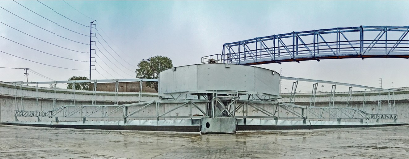
About Suction Header Clarifiers
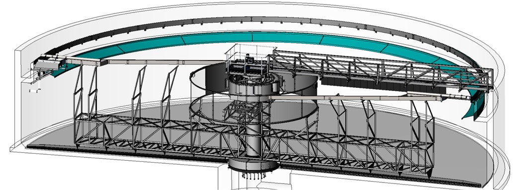
One or two round or square tapered headers stretch from a manifold radially across the bottom of the clarifier. Varying size and spaced orifices located in the leading edge of the suction header are designed to draw settled sludge at an even removal rate across the entire basin floor. Through pumping, or head differential, settled solids are drawn through the header into the manifold and out of the clarifier.
Header design starts with dividing the tank into annular rings then sizing the suction header holes to withdrawn the amount of sludge within that ring.
Hole size and ring width is adjusted to achieve a balanced withdrawal rate across the clarifier bottom.
Header size and hole size designed using an iterative process with CFD software to achieve flow balance without exceeding the minimum/maximum flow velocity throughout the header.
3D Models of Every Project
ClearStream produces a 3D model of every unit which we manufacture. These models are extremely valuable to ensure proper fit up. In addition, these models can be a useful tool for operators training and understanding of the unit design and operation. ClearStream provides these 3D models as well as the means for clients to view and manipulate these models at their own site or offices. This affords operations and maintenance personnel with a unique opportunity to “inspect” the unit prior to any planned maintenance without having to drain the tank.

Advantages:
- Rapid removal of solids across the whole clarifier floor.
Disadvantages:
- Potential plugging of the suction header holes at low RAS removal rates.
- If the actual RAS flow rate is different than designed for, the header may draw solids at an uneven rate across the basin floor.
- Because the header draws equal to the area it rotates through, a
sludge blanket must be maintained over the entire clarifier deeper
than the suction header. - A seal must be maintained between the rotating manifold, the clarifier
center column, and the tank floor. High head differentials for the
suction header may cause the seals to collapse or “suck in” rendering
them useless. - The seals must be replaced approximately every 5 – 7 years.
Variations:
- Install a segmented rake as one arm opposite the suction header to aid
in redistribution of the sludge on the bottom.
Have A Process Problem? Need A Solution?
Our engineers will ensure you get the support needed to solve your process problems.
